Igbt Smps Schematic / 160V 3A DC motor power supply : This is a very simple circuit;. But the constant voltage and current controller requires a common ground of output circuit, controller and the mains power supply. It is one of the simplest smps power converter techniques and is often used in ram, cpu, usb etc. Igbt inverter dc manual welding machine zx7 motherboard repair pcb. Drive the igbt and are used to calculate values like average drive voltage and the driving electric power. A linear topology would be unusable for this power (2400w).
This device has been optimized for medium frequency switch mode power supplies. These lgc devices shorten delay times, and reduce Optimized igbt is available for both low conduction loss and low switching loss. The amplitude of its output voltage reduces with the duty ratio increase, hence this circuit is limiting the duty cycle to less than 50%. Igbt inverter dc manual welding machine zx7 motherboard repair pcb.
IGBTs Boost Solar Panel Efficiency | DigiKey from www.digikey.com Features • low saturation voltage: C.t.4) 150 i lm clamped inductive load current 150 a i f @ t Drive the igbt and are used to calculate values like average drive voltage and the driving electric power. These lgc devices shorten delay times, and reduce Earlier generations of smps igbts could not really keep up with a mosfet above 100 khz, but in this case a pt igbt performs better at 150 khz. Buck converter is a type of smps circuit and dc to dc converter, where the output voltage is less than input voltage. The current output of a gate driver may or may not be sufficient to drive the igbt, so designers use transistors for current boosting. The switching frequency is around 100 khz.
Igbt improves dynamic performance and efficiency and reduced the level of audible noise.
The schematic of my switching power supply you can see below. Smps is to provide gate power supply to the driver circuit. These lgc devices shorten delay times, and reduce Optimized igbt is available for both low conduction loss and low switching loss. Features • low saturation voltage: It is one of the simplest smps power converter techniques and is often used in ram, cpu, usb etc. Drive the igbt and are used to calculate values like average drive voltage and the driving electric power. Smps igbt absolute maximum ratings parameter max. Thorough understanding of underlying principle and working of circuit, trouble shooting knowledge is essential. The switching supply uses igbt transistors and is controlled by uc3845 chip. Smps welding inverter circuit easyarc zx7 200 igbt welder an2020 23 650 v trenchstop 5 d2pak machine shorted in tecnica 164 arc160 china portable mma arc board of arc200 schematic smart single phase. This device has been optimized for medium frequency switch mode power supplies. In my article about smps's it is a topology ii.d.
High current and high voltage igbts are used to serve high power requirements. Many designers think that igbt has a cmos i/p and bipolar o/p characteristic voltage controlled bipolar device. This switching power supply was created because i needed a controllable laboratory power source for more power. This device has been optimized for medium frequency switch mode power supplies. Features • low saturation voltage:
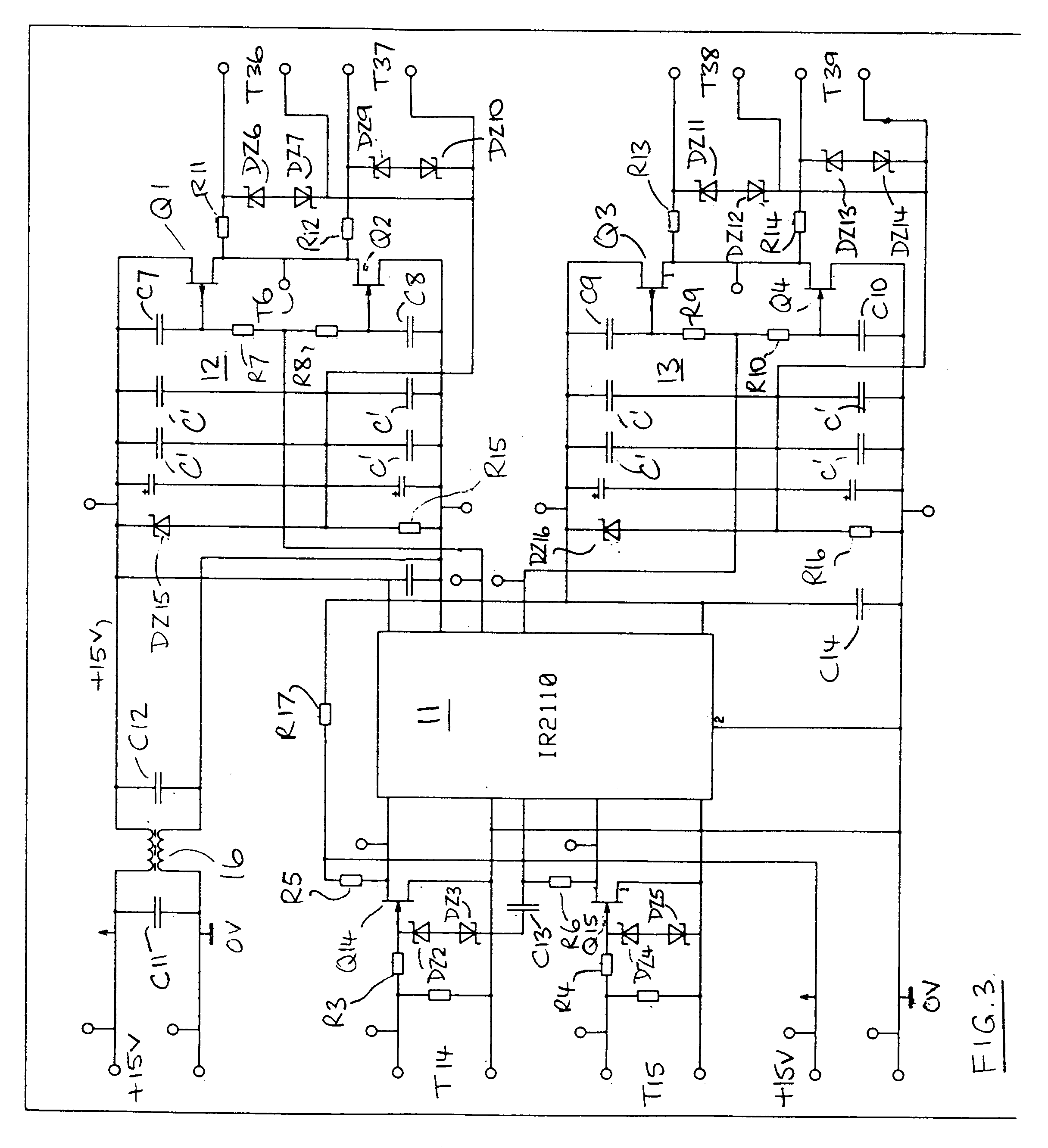
Welding Inverter Circuit Diagram | Wiring Library from patentimages.storage.googleapis.com Smps welding inverter circuit easyarc zx7 200 igbt welder an2020 23 650 v trenchstop 5 d2pak machine shorted in tecnica 164 arc160 china portable mma arc board of arc200 schematic smart single phase. The schematic of my switching power supply you can see below. This switching power supply was created because i needed a controllable laboratory power source for more power. Igbt inverter dc manual welding machine zx7 motherboard repair pcb. Typical performance curves unless otherwise. Smps igbt absolute maximum ratings parameter max. This was my dream project since last 2 yrs and i must say that care is required in each and every stage, driver circuit, 18 v power supply, igbt mounting, cooling, snubber, output diodes mounting and cooling. Features • low saturation voltage:
This was my dream project since last 2 yrs and i must say that care is required in each and every stage, driver circuit, 18 v power supply, igbt mounting, cooling, snubber, output diodes mounting and cooling.
This was my dream project since last 2 yrs and i must say that care is required in each and every stage, driver circuit, 18 v power supply, igbt mounting, cooling, snubber, output diodes mounting and cooling. In principle, a drive circuit has a forward bias power supply alternately switching back and forth using switch s A linear topology would be unusable for this power (2400w). Smps welding inverter circuit inverter welder circuit projects. This switching power supply was created because i needed a controllable laboratory power source for more power. Typical performance curves unless otherwise. This device has been optimized for medium frequency switch mode power supplies. Design and implementation of the smps for igbt driver 1hardik khambhadiya and 2prof. The diode type is specified in figure 20. High current and high voltage igbts are used to serve high power requirements. The input dc in buck converter can be a rectified ac or a battery. Igbt driver circuit for inverter. This is a very simple circuit;
This was my dream project since last 2 yrs and i must say that care is required in each and every stage, driver circuit, 18 v power supply, igbt mounting, cooling, snubber, output diodes mounting and cooling. Many designers think that igbt has a cmos i/p and bipolar o/p characteristic voltage controlled bipolar device. P.n.kapil 1pg scholar and 2assistant professor, 1,2electrical department, institute of technology, nirma university, ahmedabad, india abstract— nowadays, mosfet and insulated gate bipolar transistor (igbt) drives supplies are a great source of interest This approach works well in switch mode power supply (smps) circuits, where the frequency is high and the duty cycle ratio is small. Simplified diagram of primary inverter welding machine circuits.
160V 3A DC motor power supply from ludens.cl The mosfet t2 circuit controls, which helps to make tr2 transformer work offers floating drive and galvanic isolation for the upper igbt. Optimized igbt is available for both low conduction loss and low switching loss. Design and implementation of the smps for igbt driver 1hardik khambhadiya and 2prof. Smps welding inverter circuit inverter welder circuit projects. The input dc in buck converter can be a rectified ac or a battery. This switching power supply was created because i needed a controllable laboratory power source for more power. These lgc devices shorten delay times, and reduce This is a very simple circuit;
It is one of the simplest smps power converter techniques and is often used in ram, cpu, usb etc.
Features • low saturation voltage: The mosfet t2 circuit controls, which helps to make tr2 transformer work offers floating drive and galvanic isolation for the upper igbt. Igbt driver board pspc 420 62 for 50a 600a 1200v 1700v 34mm. The diode type is specified in figure 20. Smps is to provide gate power supply to the driver circuit. Earlier generations of smps igbts could not really keep up with a mosfet above 100 khz, but in this case a pt igbt performs better at 150 khz. Drive the igbt and are used to calculate values like average drive voltage and the driving electric power. Igbt improves dynamic performance and efficiency and reduced the level of audible noise. The amplitude of its output voltage reduces with the duty ratio increase, hence this circuit is limiting the duty cycle to less than 50%. In principle, a drive circuit has a forward bias power supply alternately switching back and forth using switch s The input dc in buck converter can be a rectified ac or a battery. But the constant voltage and current controller requires a common ground of output circuit, controller and the mains power supply. In fact, the igbt has the lowest total loss in spite of its smallest die size.